Skip to content
Machinery SpecialistForestry Attachment Guide
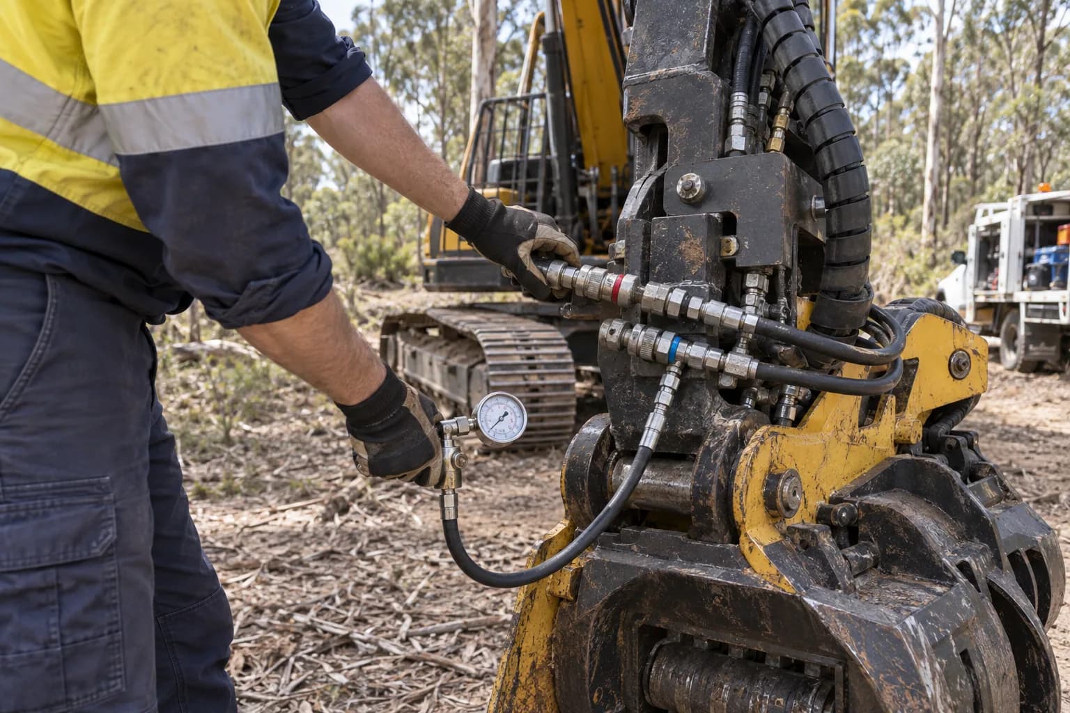
Excavator auxiliary hoses, couplers and hydraulic service points being inspected

T02 · Carrier inspection · circuit logic

How to identify an excavator hydraulic circuit before buying an attachment

The short answer

Trace the hoses and controls rather than counting couplers. Confirm whether flow is one-way or reversible, whether a low-pressure case drain returns independently to tank, and whether two attachment functions can operate at the same time. Then verify the result against the machine manual and a functional test.

Procedure

Complete the work in this order

  1. 01

    Read the machine configuration

    Use the model and serial number to obtain the correct hydraulic schematic or option list. Excavators of the same model can leave the factory with different auxiliary packages, and dealer-installed plumbing may not match the brochure for the base machine.

  2. 02

    Trace each line

    Follow the boom and stick plumbing from the valve area to the couplers. Identify supply, return, drain and any second auxiliary pair. A small line is not automatically a case drain, and a capped line is not proof that its valve and controls are installed.

  3. 03

    Test direction and control

    With a competent operator and safe connection, confirm which pedal, joystick button or monitor mode activates each port. Establish whether the circuit latches, reverses and proportions flow. Record whether another function can be used simultaneously.

  4. 04

    Verify the drain path

    A case drain should provide a low-restriction path to tank within the attachment manufacturer’s back-pressure limit. Confirm where it terminates and measure pressure if a piston motor depends on it. Never assume the normal return line performs the same function.

  5. 05

    Create a circuit schedule

    Write one page listing each port, coupler, control, direction, flow setting, pressure setting and drain limit. Give it to attachment suppliers with the carrier data so quotations are based on the installed machine rather than a generic tonne class.

The four arrangements buyers encounter

A one-way hammer circuit powers tools that require pressure in one direction and return oil in the other. A double-acting circuit reverses supply and return for cylinders or bidirectional motors. A case drain is a separate low-pressure leakage path for some motors. A dual auxiliary setup provides independent control for functions such as grip, saw and rotation.

Coupler count can mislead. A machine may have two large couplers for one reversible circuit, a small drain, and electrical controls that change behaviour by monitor mode. Conversely, hoses may be fitted along the boom without the valve section or software required to operate them. Function, not appearance, defines the circuit.

Translate attachment functions into circuits

List every action the head performs and which must occur together. A basic shear may need one double-acting function. A grinder may need a supply, unrestricted return and case drain. A grapple saw can require independent grip, saw and rotation so the operator maintains control of a section while cutting and placing it.

If functions are combined through diverter valves, ask what the operator loses during switching and how the safe state is maintained. A technically operable installation can still produce a slow or awkward cycle. The correct match covers simultaneous control, return limits and cooling as well as nominal litres per minute.

Common mistakes

Counting hoses

Hose quantity does not reveal direction, valve control or the path back to tank.

Calling every small line a drain

Pilot, leakage and auxiliary lines serve different purposes and pressure ratings.

Ignoring simultaneous functions

A diverter may make every function possible but prevent the productive sequence.

Trusting the model brochure

Optional and dealer-installed circuits vary within the same excavator model.

Continue the job

Measure auxiliary flow

Put verified numbers against the identified circuit.

Set up a case drain

Protect motors that require an independent drain path.

Grapple saw guide

See why multi-function heads expose circuit limitations.
More field procedures

Keep building the machine record

Technician checking hydraulic hoses and test equipment on an excavator attachment circuit
T01

Measure auxiliary flow

Use a calibrated flow meter and load valve at normal operating temperature, test the intended auxiliary circuit in both required directions, and record flow at the attachment manufacturer’s working pressure. The machine’s advertised pump output is not the number the attachment receives.

Open tutorial →
Excavator auxiliary hoses, couplers and hydraulic service points being inspected
T02

Identify the hydraulic circuit

Trace the hoses and controls rather than counting couplers. Confirm whether flow is one-way or reversible, whether a low-pressure case drain returns independently to tank, and whether two attachment functions can operate at the same time. Then verify the result against the machine manual and a functional test.

Open tutorial →
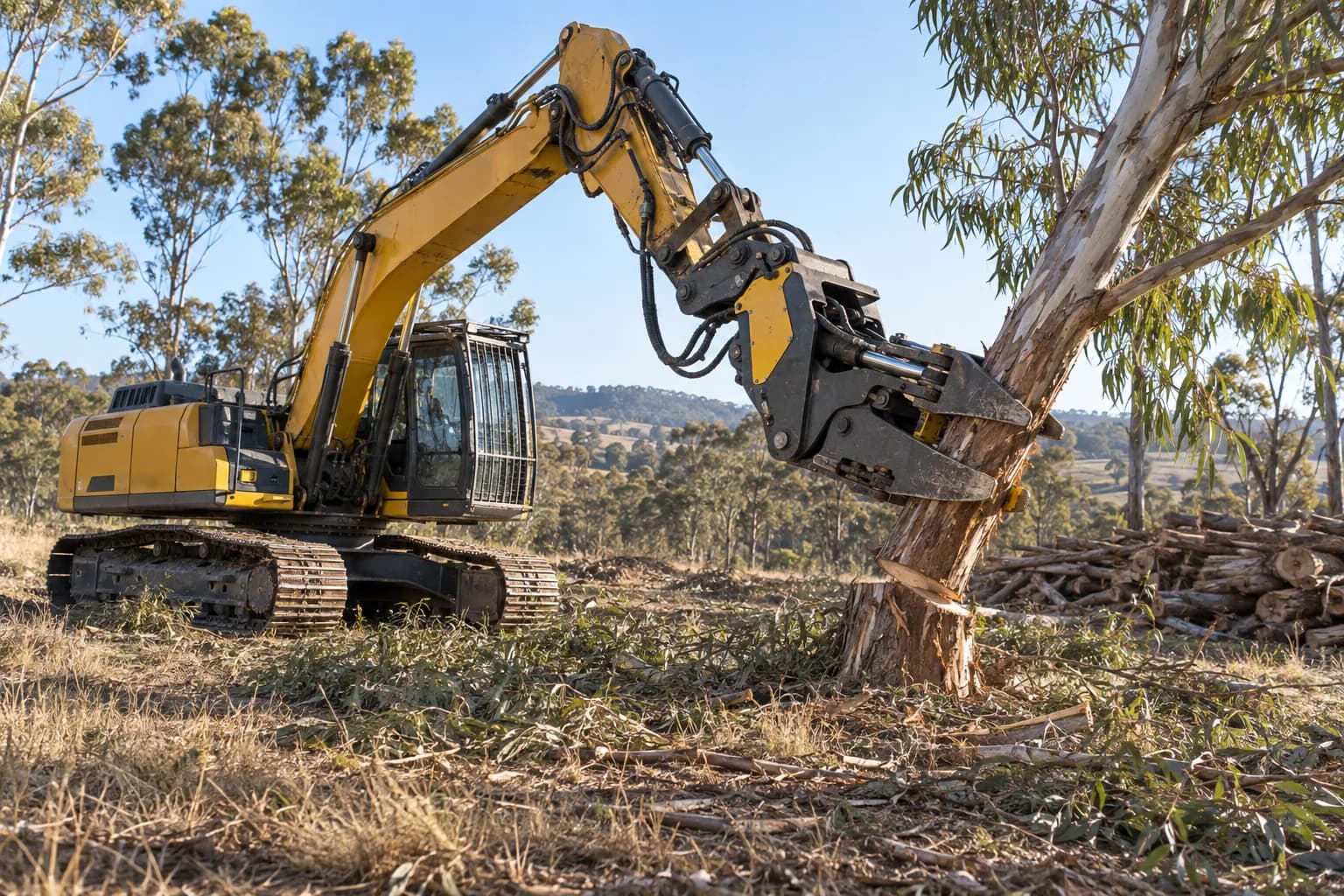
Forestry excavator holding a cut tree section with an attachment at working radius
T03

Size an attachment to a carrier

Treat published carrier tonnes as an initial filter. The final match requires attachment mass with bracket and rotator, excavator lift capacity at the actual radius and sector, usable hydraulic flow and pressure, transport configuration, guarding, and the maximum material the head will retain.

Open tutorial →
Forestry attachments and excavators prepared in a machinery yard for installation and commissioning
T04

Install and commission an attachment

Commission the ordered attachment as one installed system. Verify identity and mass, mechanical fit, hose routing, hydraulic settings, control logic, guarding and transport before loading it on representative material. Record baseline pressures, temperatures, cycle times and operator limits for future troubleshooting.

Open tutorial →
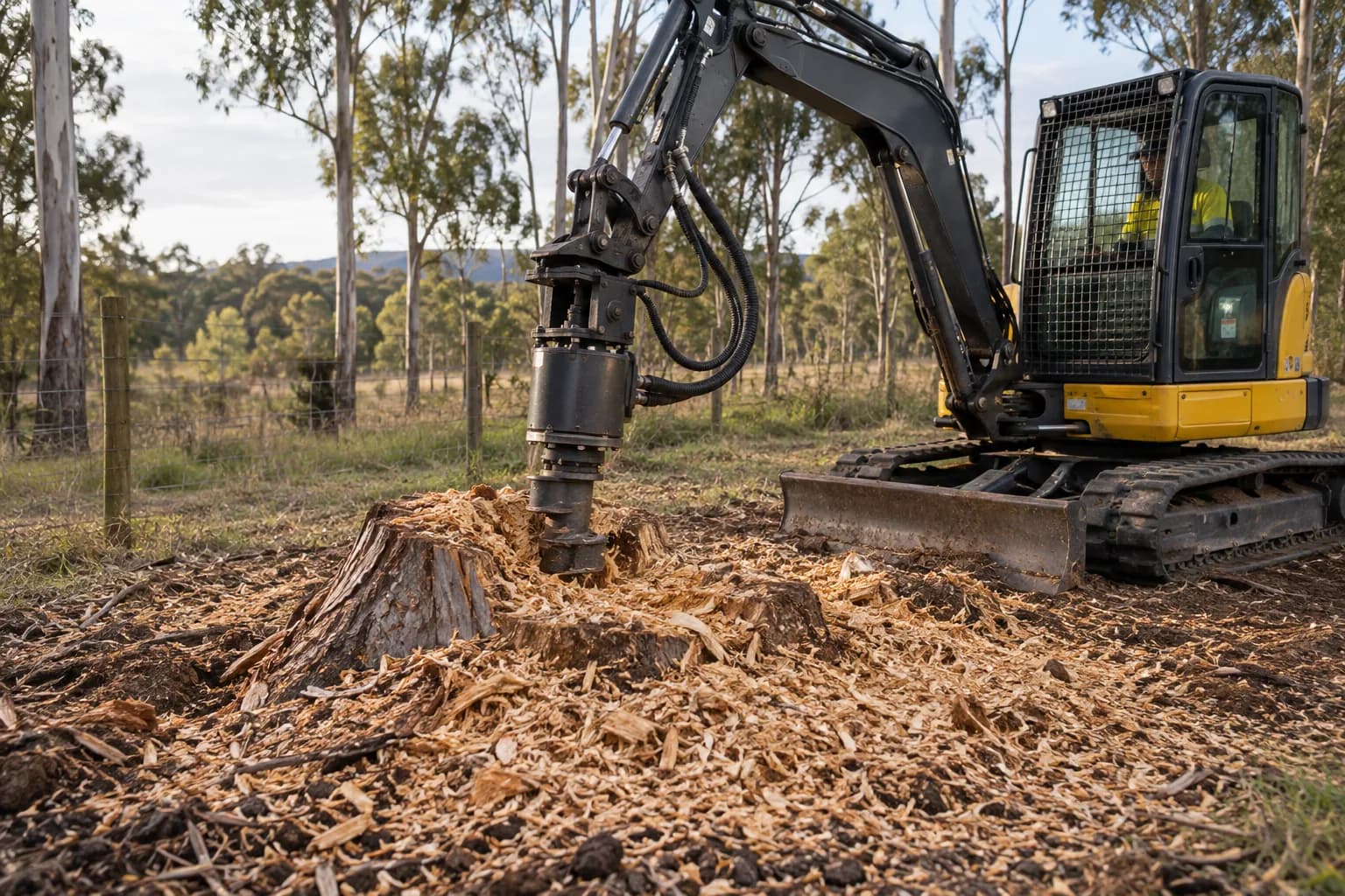
Excavator-mounted stump grinder with hydraulic supply, return and case-drain hoses visible
T05

Set up a case drain

Route the motor’s case-drain port through a dedicated, correctly sized, low-restriction line to the approved tank connection. Confirm the attachment manufacturer’s maximum drain pressure and measure it at working temperature. Never cap the port or tee it casually into a pressurised return.

Open tutorial →
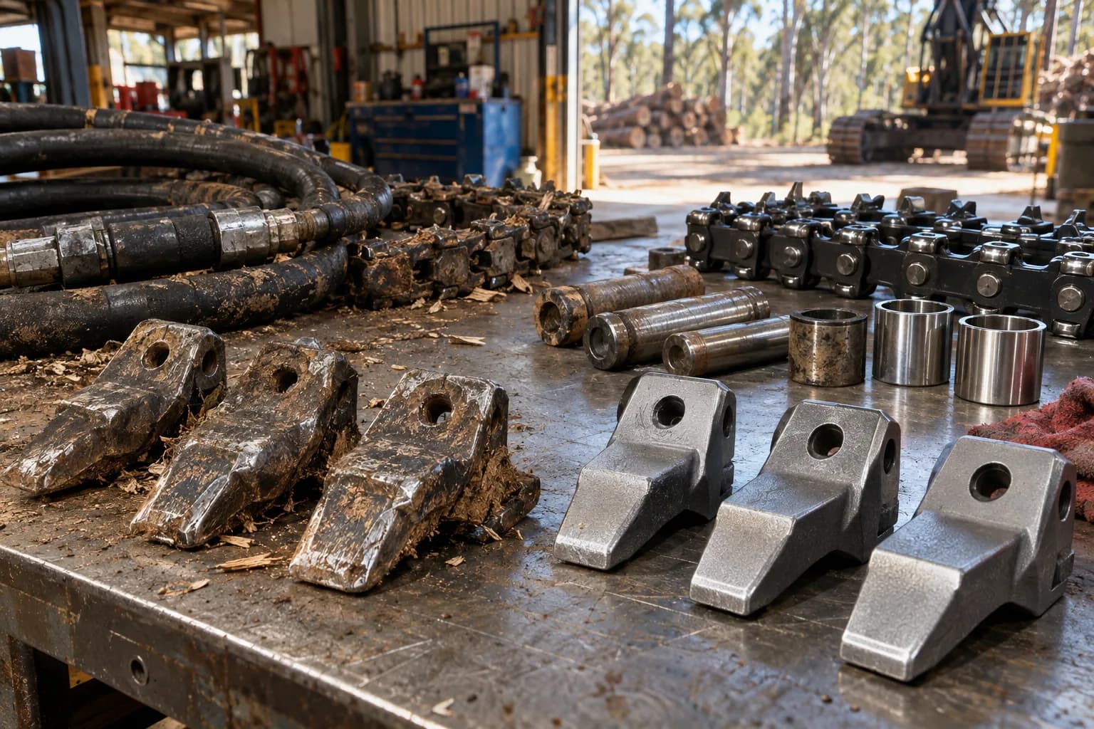
Forestry attachment wear parts, tools and components arranged on a workshop bench for inspection
T06

Inspect a used attachment

Identify the exact model and serial first, then inspect structure, pins, bearings, wear system, hydraulics, controls and supplied fitment as separate cost lines. Test the head hot on representative material and price every missing bracket, hose, controller and overdue wear item before comparing it with a complete new quotation.

Open tutorial →
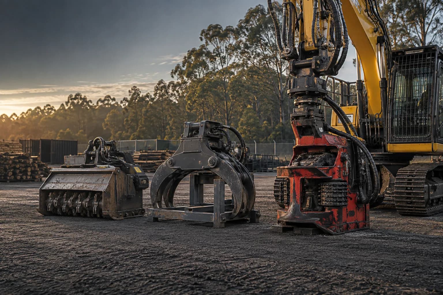
Forestry machinery fleet in an Australian equipment yard representing ownership and tender costs
T07

Calculate a tender rate

Choose the unit the client accepts, estimate completed units per productive hour from comparable work, calculate the full hourly cost of carrier, attachment and crew, then add mobilisation, wear variability, downtime, overhead, risk and margin explicitly. Do not turn a demonstration cycle into an all-in hectare or stump rate.

Open tutorial →
Forestry attachment wear parts, hand tools and service items organised on a workshop bench
T08

Build a wear-parts kit

Stock parts by failure consequence, consumption rate and replenishment lead time—not by what is cheapest. Carry enough teeth, blades, chains, hoses, couplers, fasteners and service tools to protect the next work period, with every item matched to the exact attachment serial range and a reorder point recorded.

Open tutorial →