Skip to content
Machinery SpecialistForestry Attachment Guide
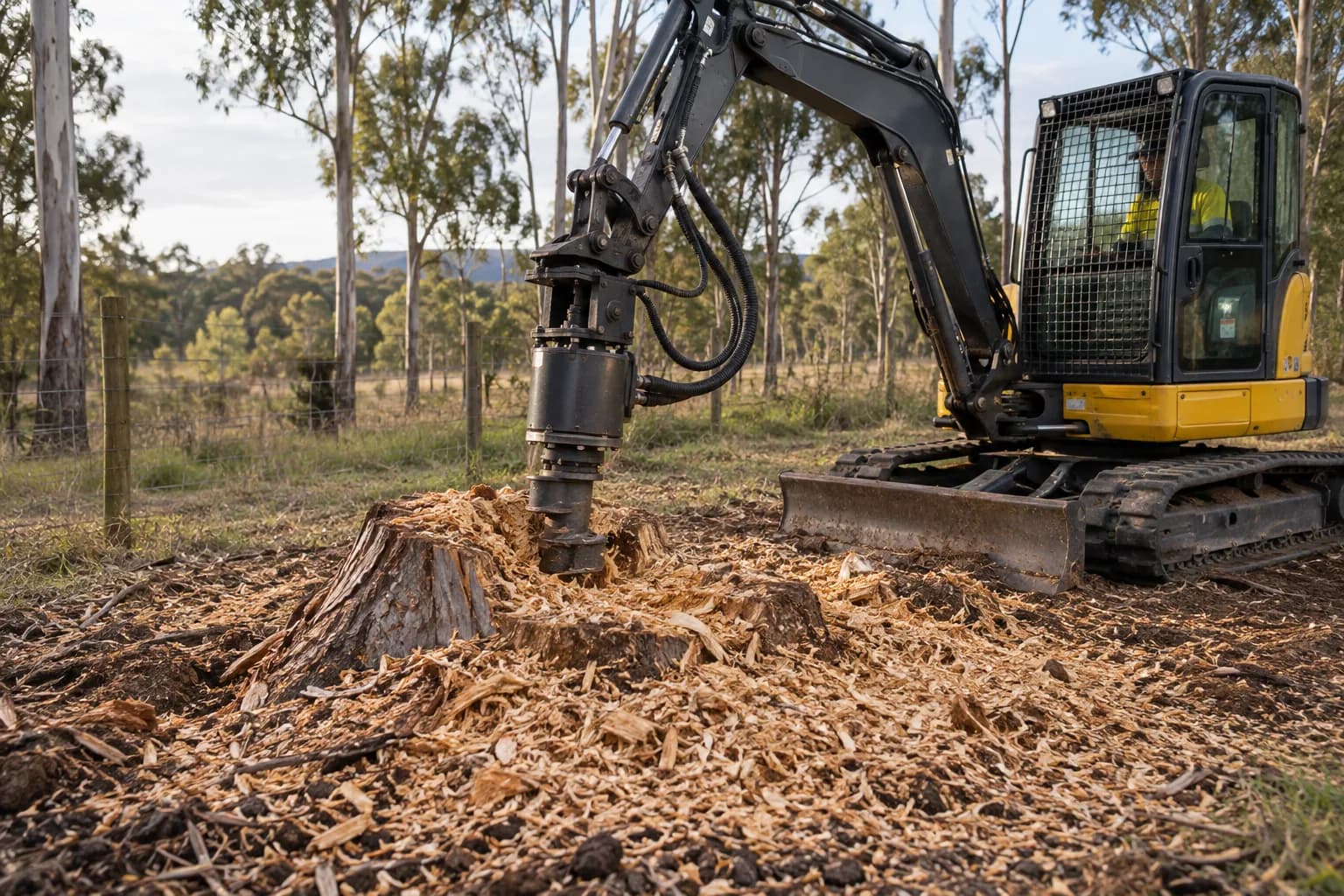
Excavator-mounted stump grinder with hydraulic supply, return and case-drain hoses visible

T05 · Motor protection · low-pressure return

How to set up a hydraulic case drain for an excavator attachment

The short answer

Route the motor’s case-drain port through a dedicated, correctly sized, low-restriction line to the approved tank connection. Confirm the attachment manufacturer’s maximum drain pressure and measure it at working temperature. Never cap the port or tee it casually into a pressurised return.

Procedure

Complete the work in this order

  1. 01

    Confirm that the motor requires it

    Use the attachment manual and motor specification. Identify the case-drain port and maximum permitted pressure. Some motors have multiple drain ports for mounting orientation; the correct connection prevents the housing from trapping leakage oil.

  2. 02

    Identify the carrier tank connection

    Find the excavator manufacturer’s approved low-pressure return point. Confirm filtration requirements and whether the port is direct to tank or passes through components that add restriction. Do not select a convenient small coupler by appearance.

  3. 03

    Size and route the line

    Use the required hose bore and pressure rating, minimising restrictive fittings, sharp bends and long small-bore runs. Route for full attachment articulation without crushing or snagging and protect the coupler from contamination during changeover.

  4. 04

    Prevent incorrect connection

    Use distinct couplers, colour coding and durable labels so the drain cannot be confused with pilot or pressure lines. Document the connection order. Where practical, make the main attachment functions impossible to connect while the drain remains capped.

  5. 05

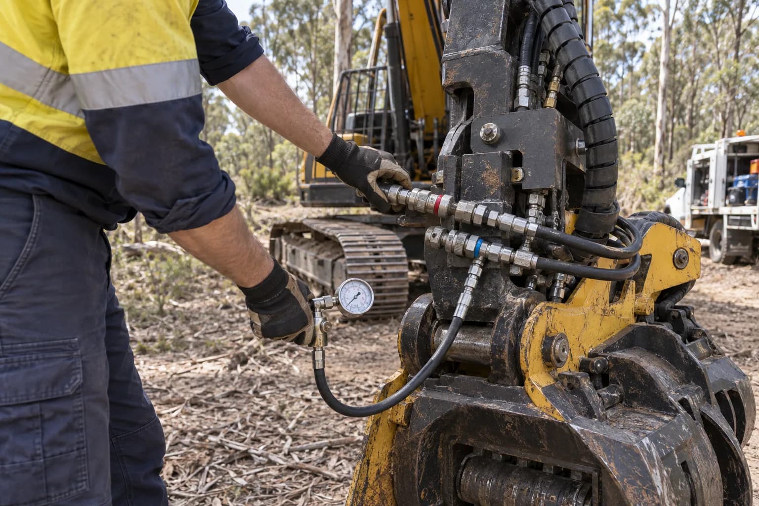
    Measure drain pressure hot

    Install a suitable gauge at the specified point and test through the normal operating range after the oil reaches working temperature. Record pressure at idle, normal load and any high-load condition, then retain the result as part of commissioning.

What the case drain actually does

Hydraulic motors leak a controlled amount of oil internally for lubrication and component clearance. That oil collects in the housing and needs a low-pressure path back to tank. If housing pressure rises beyond the seal design, leakage becomes failure: shaft seals can push out, oil can contaminate the attachment and the motor may be damaged.

The normal motor return carries working flow and can experience pressure from valves, couplers, filters and hose restriction. A case drain carries much less flow but has a stricter pressure limit. The two lines are therefore not interchangeable merely because both ultimately return oil to the reservoir.

Treat drain condition as a diagnostic signal

A rising drain flow can indicate internal motor wear, while rising drain pressure can indicate a restriction downstream. Establishing a new-machine baseline gives technicians something to compare with later. Record the test method and temperature because cold oil and different gauge locations can change the number.

If seals repeatedly fail, do not simply replace them. Verify the drain is connected, unobstructed and within the motor limit across the full cycle. Check couplers, crushed hoses, tank ports and any shared return arrangement. Repeated seal failure is often a circuit symptom rather than a defective seal.

Common mistakes

Capping the port

Internal leakage then pressurises the motor housing and attacks the shaft seal.

Teeing into the main return

Return-line pressure spikes can be transmitted directly into the motor case.

Using undersized couplers

A small restriction is enough to exceed a low case-pressure limit when oil is hot.

Testing only at idle

The damaging condition may appear only under full load and normal operating temperature.

Continue the job

Stump grinder guide

See where piston motors make drainage critical.

Identify the circuit

Distinguish the drain from normal auxiliary plumbing.

Hydraulic troubleshooting

Diagnose heat, leaks and lost performance systematically.
More field procedures

Keep building the machine record

Technician checking hydraulic hoses and test equipment on an excavator attachment circuit
T01

Measure auxiliary flow

Use a calibrated flow meter and load valve at normal operating temperature, test the intended auxiliary circuit in both required directions, and record flow at the attachment manufacturer’s working pressure. The machine’s advertised pump output is not the number the attachment receives.

Open tutorial →
Excavator auxiliary hoses, couplers and hydraulic service points being inspected
T02

Identify the hydraulic circuit

Trace the hoses and controls rather than counting couplers. Confirm whether flow is one-way or reversible, whether a low-pressure case drain returns independently to tank, and whether two attachment functions can operate at the same time. Then verify the result against the machine manual and a functional test.

Open tutorial →
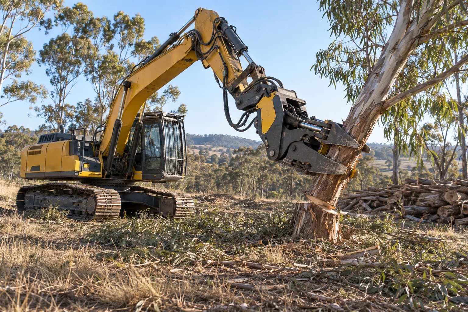
Forestry excavator holding a cut tree section with an attachment at working radius
T03

Size an attachment to a carrier

Treat published carrier tonnes as an initial filter. The final match requires attachment mass with bracket and rotator, excavator lift capacity at the actual radius and sector, usable hydraulic flow and pressure, transport configuration, guarding, and the maximum material the head will retain.

Open tutorial →
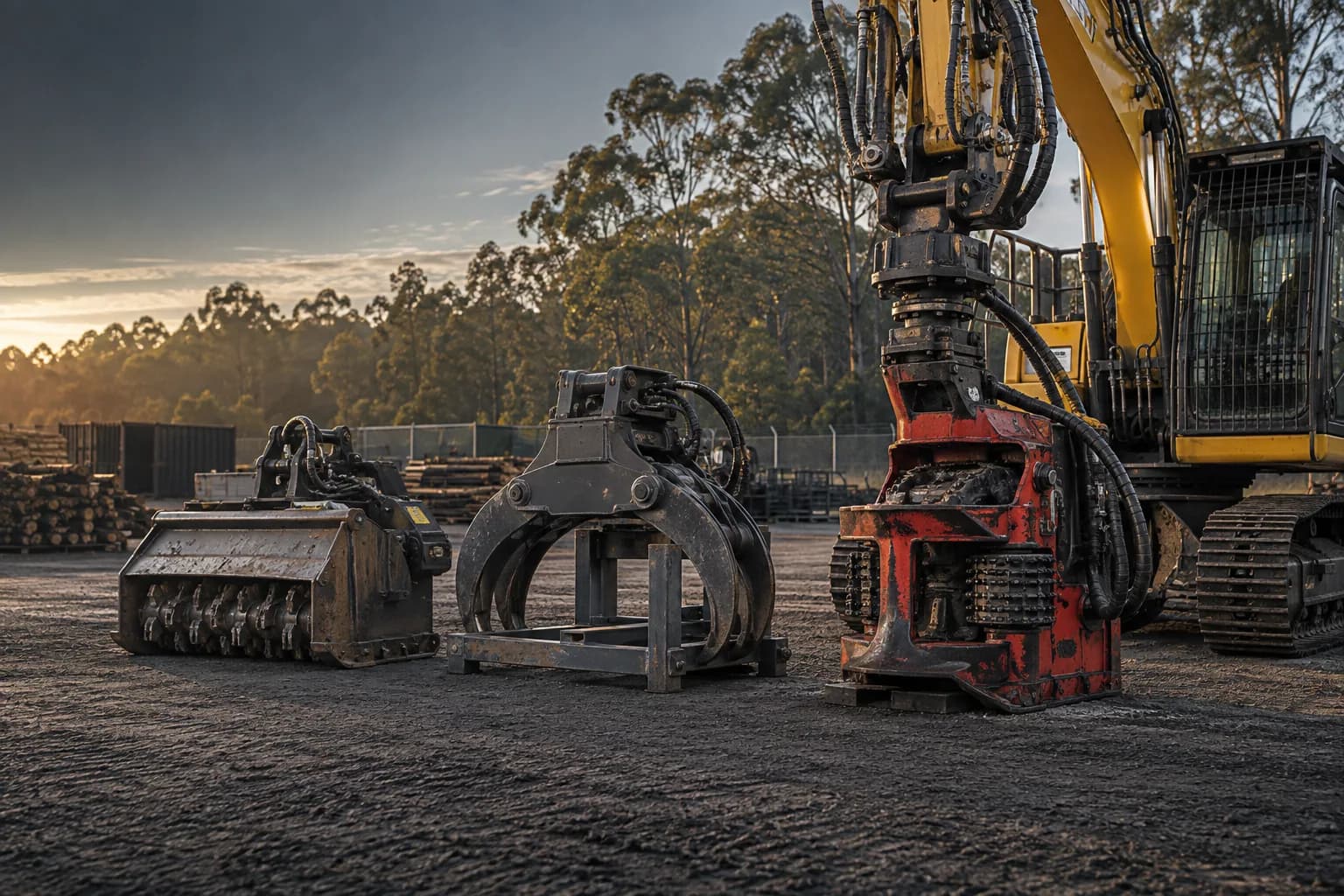
Forestry attachments and excavators prepared in a machinery yard for installation and commissioning
T04

Install and commission an attachment

Commission the ordered attachment as one installed system. Verify identity and mass, mechanical fit, hose routing, hydraulic settings, control logic, guarding and transport before loading it on representative material. Record baseline pressures, temperatures, cycle times and operator limits for future troubleshooting.

Open tutorial →
Excavator-mounted stump grinder with hydraulic supply, return and case-drain hoses visible
T05

Set up a case drain

Route the motor’s case-drain port through a dedicated, correctly sized, low-restriction line to the approved tank connection. Confirm the attachment manufacturer’s maximum drain pressure and measure it at working temperature. Never cap the port or tee it casually into a pressurised return.

Open tutorial →
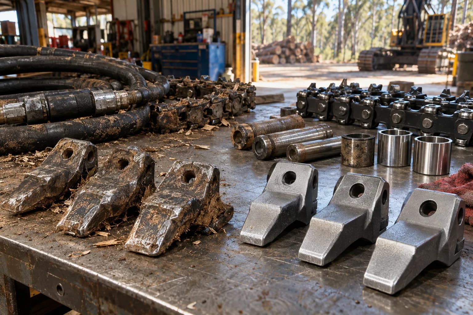
Forestry attachment wear parts, tools and components arranged on a workshop bench for inspection
T06

Inspect a used attachment

Identify the exact model and serial first, then inspect structure, pins, bearings, wear system, hydraulics, controls and supplied fitment as separate cost lines. Test the head hot on representative material and price every missing bracket, hose, controller and overdue wear item before comparing it with a complete new quotation.

Open tutorial →
Forestry machinery fleet in an Australian equipment yard representing ownership and tender costs
T07

Calculate a tender rate

Choose the unit the client accepts, estimate completed units per productive hour from comparable work, calculate the full hourly cost of carrier, attachment and crew, then add mobilisation, wear variability, downtime, overhead, risk and margin explicitly. Do not turn a demonstration cycle into an all-in hectare or stump rate.

Open tutorial →
Forestry attachment wear parts, hand tools and service items organised on a workshop bench
T08

Build a wear-parts kit

Stock parts by failure consequence, consumption rate and replenishment lead time—not by what is cheapest. Carry enough teeth, blades, chains, hoses, couplers, fasteners and service tools to protect the next work period, with every item matched to the exact attachment serial range and a reorder point recorded.

Open tutorial →