The short answer
Use a calibrated flow meter and load valve at normal operating temperature, test the intended auxiliary circuit in both required directions, and record flow at the attachment manufacturer’s working pressure. The machine’s advertised pump output is not the number the attachment receives.
Procedure
Complete the work in this order
- 01
Collect the machine data
Record model, serial range, operating configuration, coupler, auxiliary circuit type, published pump output and relief setting. Photograph the monitor settings and couplers. These details let the supplier distinguish a machine limitation from a setting, plumbing or test problem.
- 02
Warm the hydraulic system
Bring the excavator to its normal working temperature using a safe operating cycle. Cold oil can make a marginal circuit appear stronger than it is. A forestry mulcher or grinder imposes sustained load, so a cold five-minute reading is not representative.
- 03
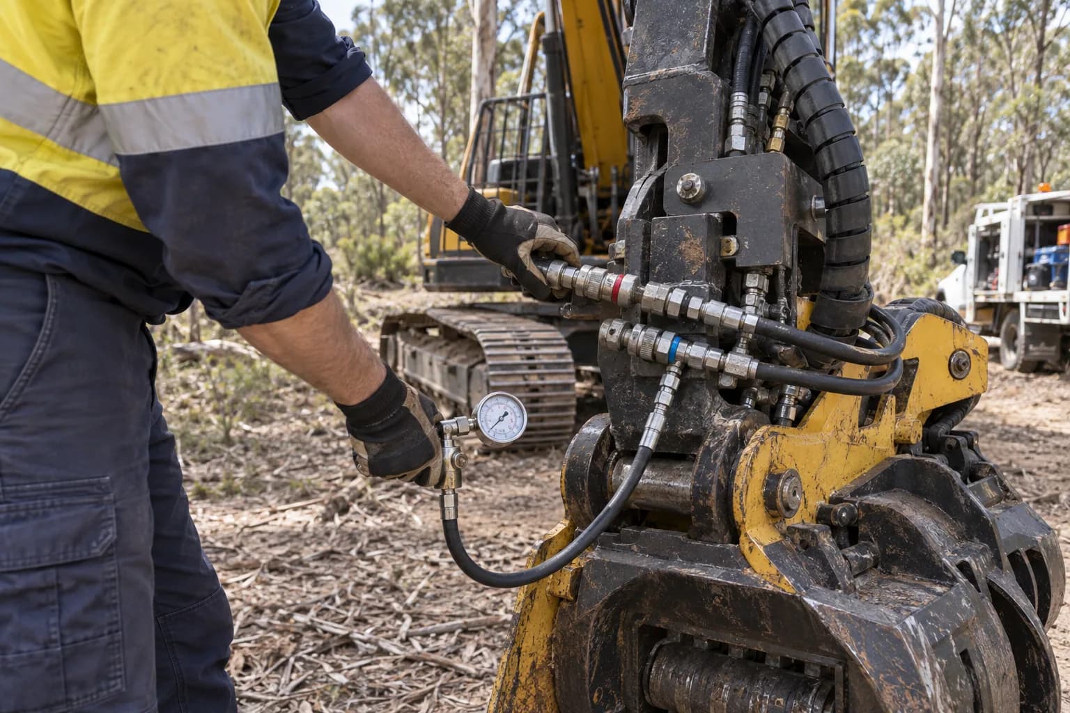
Connect a rated flow meter
Use hoses, fittings and a meter rated above the machine’s maximum pressure and flow. Connect in the same path the attachment will use, including the intended quick couplers. Do not improvise a restriction or open a pressurised line to estimate flow.
- 04
Load the circuit progressively
Run the engine at the operating speed intended for the attachment, then increase the load valve gradually. Record litres per minute at several pressures, particularly the attachment’s nominated working pressure. Stop if oil temperature, hose movement or noise becomes abnormal.
- 05
Check return and repeatability
Measure return pressure where the attachment specifies a limit and repeat the test after sustained operation. Test reverse direction for double-acting functions. Save the result with date, oil temperature, engine speed, monitor setting and the person who performed the test.
Why published pump flow is not usable attachment flow
An excavator specification may state total pump output, combined pump flow or a maximum auxiliary setting. Steering, travel, boom functions, control valves, hose diameter and relief behaviour all sit between that number and the attachment motor. The useful figure is the stable flow available at the pressure the tool needs while the machine is hot.
A flow-only reading is incomplete. A circuit delivering a high number at almost no resistance may collapse as the load valve approaches working pressure. Record a flow-and-pressure curve or at least several paired readings. That evidence lets an attachment supplier select a motor or model without treating the carrier class as a substitute for hydraulic data.
Interpret the result conservatively
Do not order a tool whose minimum requirement equals the best momentary result. Allow for hot oil, filter condition, normal component wear and other functions the operator uses during a cycle. Continuous tools also need cooling capacity; stable flow for ten minutes does not prove the carrier can reject heat across a full summer shift.
If the result is low, check monitor limits, circuit mode, coupler restriction, hose sizing, filters and relief settings with a competent technician. Increasing pressure or flow without confirming component ratings can damage the excavator. The goal is a verified operating envelope, not the largest number the system can produce briefly.
Common mistakes
Using total pump output
That figure may combine pumps and does not describe the attachment port under load.
Testing cold oil
The result can overstate sustained performance and hide a cooling problem.
Ignoring return pressure
A restricted return creates heat, poor motor performance and seal failures.
Changing relief settings casually
More pressure is not free capacity and may exceed the rating of hoses, valves or the attachment.
Continue the job
Hydraulic flow calculator
Compare measured results with every attachment category.
Carrier compatibility
Combine hydraulics with weight and lift capacity.
Identify the circuit
Confirm what the plumbing can actually control.